
Product and Ordering Information
| Order Code |
| HP – (Range) – (Input) |
| iTEMP PCP TMT 181 | Application: |
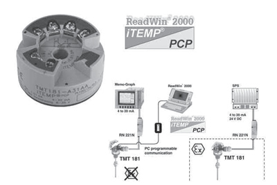 |
• Economical and technical alternative to direct wiring to DCS or PLC • PC programmable (PCP) temperature head transmitter for converting various input signals into a scalable 4 to 20 mA analog output signal • Suitable for RTD thermometers, thermocouples TC, Ohm and mV inputs • 2-wire transmitter for a linear temperature proportional analog output |
| Features and benefits | and also: |
|
• Operation, visualization and maintenance with PC, using ReadWin ® 2000 freeware • High accuracy: 0.08% of span • Breakdown information in event of sensor break or short-circuit, enables a quick maintenance intervention • Outstanding 3.75 kV AC galvanic isolation from the sensor input to the output • Online configuration during measurement using configuration kit for an easy setup • Output simulation for a quick and easy check of the loop • Customized measuring range setup or expanded SETUP, see questionnaire page 6 |
• Long term stability: <0.05% • Electromagnetic compatibility to IEC 61326 for use in noisy environments • Fully potted electronics and gold plated terminals allow humidity • Captive screws for ease of connection • Customer specific linearization • Linearization curve match improves accuracy • Approvals: FM, CSA and ATEX for high safety standards • UL recognized component to UL 3111-1 • GL German Lloyd marine approval |
| Operation and system construction | |
| Measurement principle |
Electronic monitoring and conversion of input signals in industrial temperature measurement. |
| Measurement system |
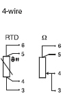
The iTEMP PCP TMT 181 temperature head transmitter is a two wire transmitter with an analog output. It has measurement input for resistance thermometers (RTD) in 2-, 3- or 4-wire connection, thermocouples and voltage transmitters. Setting up of the TMT 181 is done using the TMT 181A configuration kit. |
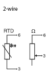
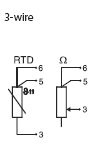
| Input – Resistance thermometer (RTD) | |||
| Input | Designation | Measurement range limits | min. span |
|
to IEC 751 (a = 0.00385) |
Pt100 Pt500 Pt1000 |
-328 to 1562 °F (-200 to 850 °C) -328 to 482 °F (-200 to 250 °C) -328 to 482 °F (-200 to 250 °C) |
18 °F (10 °C) 18 °F (10 °C) 18 °F (10 °C) |
|
to DIN 43760 (a = 0.00618) |
Ni100 Ni500 Ni1000 |
-76 to 356 °F (-60 to 180 °C) -76 to 302 °F (-60 to 150 °C) -76 to 302 °F (-60 to 150 °C) |
18 °F (10 °C) 18 °F (10 °C) 18 °F (10 °C) |
| Connection type | 2-, 3- or 4-wire connection cable resistance compensation possible in the 2 wire system (0 to 20 Ω) | ||
| Sensor cable resistance | max. 11 Ω per cable | ||
| Sensor current | £ 0.6 mA | ||
| Input – Resistance transmitter (Ω) | |||
| Designation | Measurement range limits |
min. measurem. range |
|
| Resistance (Ω) |
10 to 400 Ω 10 to 2000 Ω |
10 Ω 100 Ω |
|
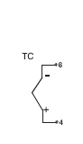
| Input – Thermocouples (TC) | |||
| Input | Designation | Measurement range limits | min. measurement range |
|
to NIST Monograph 175, IEC 584 |
Type B (PtRh30-PtRh6) [1] Type E (NiCr-CuNi) Type J (Fe-CuNi) Type K (NiCr-Ni) Type N (NiCrSi-NiSi) Type R (PtRh13-Pt) Type S (PtRh10-Pt) Type T (Cu-CuNi) |
32 to 3308 °F (0 to +1820 °C) -328 to 1679 °F (-200 to + 915 °C) -328 to 2192 °F (-200 to +1200 °C) -328 to 2501 °F (-200 to +1372 °C) -454 to 2372 °F (-270 to +1300 °C) 32 to 3214 °F (0 to +1768 °C) 32 to 3214 °F (0 to +1768 °C) -328 to 752 °F (-200 to + 400 °C) |
900 °F (500 °C) 90 °F (50 °C) 90 °F (50 °C) 90 °F (50 °C) 90 °F (50 °C) 900 °F (500 °C) 900 °F (500 °C) 90 °F (50 °C) |
|
to ASTM E988 |
Type C (W5Re-W26Re) Type D (W3Re-W25Re) |
32 to 4208 °F (0 to +2320 °C) 32 to 4523 °F (0 to +2495 °C) |
900 °F (500 °C) 900 °F (500 °C) |
| to DIN 43710 |
Type L (Fe-CuNi) Type U (Cu-CuNi) |
-328 to 1652 °F (-200 to + 900 °C) -328 to 1112 °F (-200 to + 600 °C) |
90 °F (50 °C) 90 °F (50 °C) |
| Cold junction | internal (Pt100) or external , 32 to 176 °F (0 to 80 °C) | ||
| Accuracy of cold junction | ± 1.8 °F (± 1 °C) | ||
| Sensor current | 30 nA | ||
| Input – Voltage transmitters (mV) | |||
| Designation | Measurement range limits | min. measurem. range | |
| Millivolt transmitter (mV) | -10 to 100 mV | 5 mV | |
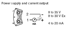
| Output – Output (analogue) | |||
|
Output (analogue) Output signal |
4 to 20 mA, 20 to 4 mA | ||
| Transmission behavior | temperature linear, resistance linear, voltage linear | ||
| Source impedance | Vpower supply – 8 V) / 0.025 A (current output) e. g. (24 V – 8 V)/0.025 A = 640 Ω | ||
|
Digital Filter 1st degree |
0 to 8 s | ||
| Input current required | ≤ 3.5 mA | ||
| Current limit | ≤ 25 mA | ||
| Switch on delay | 4 s (during power up Ia = 3.8 mA) | ||
| Reply time | 1 s | ||
Breakdown information to NAMUR NE 43
Breakdown information is created when the measuring information is invalid or not present
anymore and gives a complete listing of all errors occurring in the measuring system.
| Signal (mA) | ||
| Under ranging | Standard | 3.8 |
| Over ranging | Standard | 20.5 |
|
Sensor break; sensor short circuit low |
To NAMUR NE 43 | ≤ 3.6 |
|
Sensor break; sensor short circuit high |
To NAMUR NE 43 | ≤ 21.5 |
| Electrical connection | |||
| Power supply | Ub = 8 to 35 V DC, polarity protected | ||
| Galvanic isolation (In/out) | Û = 3.75 kV AC | ||
| Allowable ripple | Uss ≤ 5 V at Ub ≥ 13 V, f max. = 1 kHz | ||
| Accuracy | |||
| Reference conditions | Calibration temperature 73.4 °F ± 9 °F (23 °C ± 5 °C) | ||
| Accuracy – Resistance thermometer (RTD) | |||
| Type | Measurement accuracy [1] | ||
|
Pt100, Ni100 Pt500, Ni500 Pt1000, Ni1000 |
0.36 °F (0.2 °C) or 0.08% 0.9 °F (0.5 °C) or 0.20% 0.54 °F (0.3 °C) or 0.12% |
||
| Accuracy – Resistance transmitter (Ω) | |||
| Type | Measurement accuracy [1] | Measurement range | |
| Resistance (Ω) | ± 0.1 Ω or 0.08% | 10 to 400 Ω | |
| ± 1.5 Ω or 0.12% | 10 to 2000 Ω | ||
| Accuracy – Thermocouples (TC) | |||
| Type | Measurement accuracy [1] | ||
|
K, J, T, E, L, U N, C, D S, B, R MoRe5-MoRe41 |
typ. 0.9 °F (0.5 °C) or 0.08% typ. 1.8 °F (1.0 °C) or 0.08% typ. 3.6 °F (2.0 °C) or 0.08% |
||
| Influence of the internal reference junction | Pt100 DIN IEC 751 Cl. B | ||
| Accuracy – Voltage transmitters (mV) | |||
| Type | Measurement accuracy [1] | Measurement range | |
| Millivolt transmitter (mV) | ± 20 uV or 0.08% | -10 to 100 mV | |
|
Influence of power supply |
≤ ±0.01%/V deviation from 24 V [2] |
| Load influence | ≤ ±0.02%/100 Ω [2] |
[1 ] % is related to the adjusted measurement range (the value to be applied is the greater)
[2] Values refer to the full scale value
| Temperature drift |
Resistive thermometer (RTD): Td = ± (8.3 ppm/°F * max. meas. range + 27.8 ppm/°F * preset meas. range) * Δθ Resistive thermometer Pt100: Td= ±(8.3 ppm/°F * (range end value + 200) + 27.8 ppm/°F * preset meas. range) * Δθ Thermocouple (TC): Td= ±(27.8 ppm/°F * max. meas. range + 27.8 ppm/°F * preset meas. range) * Δθ Δθ = Deviation of the ambient temperature accord. to the reference condition (73.4 ° F ± 9 °F) |
| Long term stability | ≤ 0.18 °F/Year ( ≤ 0.1 °C/Year) [1] or ≤ 0.05%/Year [1][2] |
| Installation conditions | |||
| Installation angle | No limit | ||
| Installation area | Connection head accord. to DIN 43 729 Form B; TAF 10 field housing | ||
| Application conditions – Ambient conditions | |||
| Ambient temperature | -40 to 185 °F (-40 to +85 °C), for Ex-areas see Ex-certification or control drawing | ||
| Storage temperature | -40 to 212 °F (-40 to +100 °C) | ||
| Climatic class | As per IEC 60 654-1, Class C | ||
| Moisture condensation | Allowed | ||
| Ingress protection | IP 00 / NEMA 4 (IP66) installed in TAF 10 field housing | ||
| Vibration protection | 4g / 2 to 150 Hz according to IEC 60 068-2-6 | ||
| EMC immunity – CE Electromagnetic Compatibility Compliance | |||
| The device meets all requirements listed under IEC 61326 Amendment 1, 1998 and NAMUR NE 21. This recommendation is an uniform and practical way of determining whether the devices used in laboratory and process control are immune to interference with an objective to increase its functional safety. | |||
| Discharge of static electricity | IEC 61000-4-2 | 6 kV cont., 8 kV air | |
| Electromagnetic fields | IEC 61000-4-3 | 80 to 1000 Hz, 10 V/m | |
| Burst (signal) | IEC 61000-4-4 | 1 kV; 2 kV (B)[3] | |
| Transient voltage | IEC 61000-4-5 | 1 kV unsym./0.5 kV sym. | |
| HF coupling | IEC 61000-4-6 | 0.15 to 80 Mhz, 10 V | |
| Mechanical construction | |||
| Dimensions | 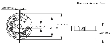 |
||
| Weight | approx. 1.4 oz (40 g) | ||
| Materials |
Housing: PC Potting: PUR |
||
| Terminals | Cable up to max. 16 AWG, secure screws | ||
[1] Values under reference operating conditions
[2] % refer to the set span. The highest value is valid
[3] self recovery.
| Mechanical construction | ||||
 |
 |
|||
 |
 |
 |
 |
 |
| Display and operating system – Remote operation | ||||
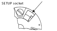
| Configuration set | Configuration kit TMT 181A-VP | |||
| Configuration | Using PC program (ReadWin ® 2000) | |||
| Interface | PC interface connection cable TTL -/- RS 232 with plug | |||
| Configurable parameters | Sensor type and connection type, engineering units (°C/°F), measurement range, internal/external cold junction compensation, cable resistance compensation on 2 wire connection, fault conditioning, output signal (4 to 20 / 20 to 4 mA), digital filter (damping), offset, measurement point identification (8 characters), output simulation | |||
| Certification | ||||
| CE mark |
This unit complies with the legal requirements laid out within the EU regulations. |
|||
| GL | Ship building approval (Germanischer Lloyd) | |||
| UL | Recognized component to UL 3111-1 | |||
| Hazardous area approvals |
FM IS, Class I, Div 1+2, Group A, B, C, D CSA IS, Class I, Div 1+2, Group A, B, C, D ATEX II 1G EEx ia IIC T6/5/4 ATEX II 3G EEx nA IIC T4/T5/T6 ATEX II 3D in compliance with EN 50281-1 |
|||
| Other standards and guidelines |
IEC 60529: Degrees of protection by housing (IP-Code) IEC 61010: Safety requirements for electrical measurement, control and laboratory instrumentation IEC 61326: Electromagnetic compatibility (EMC requirements) NAMUR: Standardization association for measurement and control in chemical and pharmaceutical industries. (www.namur.de) NEMA: Standardization association for the electrical industry |
|||