
Ceramic Protecting Tube Assembly – Angle Type For Molten Metals
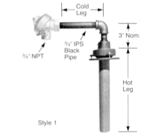
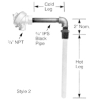
| Calibration | Element * Gauge | Style | Hot Leg ** Material | Ordering Code | |||
| Type | Head | Cold Leg
Length |
Hot Leg
Length |
||||
| Type N
Nicrosil – Nisil |
8 AWG. | 1 | SCT
(Silicon Carbide) |
N8SC | Select
from table below. |
Specify
in inches. |
|
| 14 AWG. | N14SC | ||||||
| 8 AWG. | 2*** | C30 Ceramic
C98 Ceramic |
N8C30 | ||||
| N8C98 | |||||||
| 14 AWG. | C30 Ceramic
C98 Ceramic |
N14C30 | |||||
| N14C98 | |||||||
| Type K
Chromel – Alumel |
8 AWG. | 1 | SCT
(Silicon Carbide) |
K8SC | |||
| 14 AWG. | K14SC | ||||||
| 8 AWG. | 2*** | C30 Ceramic
C98 Ceramic |
K8C30 | ||||
| K8C98 | |||||||
| 14 AWG. | C30 Ceramic
C98 Ceramic |
K14C30 | |||||
| K14C98 | |||||||
* Selection of a head from table below will determine whether a single or dual element is furnished.
** Click here for characteristics of ceramic tubes.
*** The hot leg tube of style 2 assemblies has a 3/4″ NPT male thread as standard. It is not normally required for this type of assembly, but is provided so that standard tubes can be used for fabrication.
| Terminal Head Options | ||
| Head | Terminal Block | Specify |
| Cast Iron Screw Cover | Single
Dual |
A
AD |
| Cast Aluminum Screw Cover | Single
Dual |
B
BD |
How to Order
- Select the desired calibration, wire size, style and hot leg material from the first 4 columns of the table. Specify by “Type” under ordering code.
- Select desired terminal head from table above and place its letter code next.
- Place the desired “Cold Leg” length (in inches) next.
- Place the desired “Hot Leg” length (in inches) next.
| For Example: | ||||||||
| K8C30 | – | A | – | 24 | – | 18 | ||
| Type | Head | Cold Leg | Hot Leg | |||||