
Product and Ordering Information
(See Section 100 “Cerampak Thermocouple” for Metal Sheathed Thermocouple Information)
How to Select Thermocouple Elements
The material selected for the thermocouple will be determined by the particular conditions under which it must perform.
Suggested in this catalog are a series of element sizes and types of protections desirable under broad, general conditions. For maximum efficiency, however, the customer should carefully consider his particular needs and uses in terms of how long the element must be in service, the temperatures to which it will be exposed, the atmosphere, and the desired speed of response.
Ranges of temperatures for the most commonly used thermocouple elements are shown in the Thermocouple Selection Data table. Where sensitivity for speed of response is important, select smaller gauge wires. Where longer life is a primary consideration, especially at elevated temperatures, select a heavier gauge wire.
When ordering replacement thermocouple wire or elements be certain that the type (K, S, R, etc.) corresponds to the instrument calibration for which it is intended. This information can usually be found on the face of the instrument.
Following are type of elements available and descriptions of their general use:
|
Table 1 Thermocouple Selection Data |
Bare Wire – Ceramic Insulators |
| Type of Thermocouple or Wire & Material | Wire Gauge (AWG) | Recommended Upon Temperature Limits ° F | Recommended Conditions For Use | |
| ° F | ° C | |||
|
Type E Chromel – Constantan |
8 gauge 14 gauge 20 gauge 24 gauge |
1600 1200 1005 805 |
870 650 540 430 |
Chromel-Constantan thermocouple suitable for use at temperatures up to 1600° F in vacuum, inert, mildly oxidizing or reducing atmospheres. Not subject to corrosion at cryogenic temperatures. Has highest EMF output per degree of all commonly used thermocouples. |
|
Type J Iron – Constantan |
8 gauge 14 gauge 20 gauge 24 gauge |
1400 1100 900 700 |
760 590 480 370 |
Used with or without protective tubing where deficiency of free oxygen exists. Protective tube recommended but not essential, desirable for cleanliness and longer service. Since JP wire oxidizes rapidly above 1000° F, compensate by using larger gauge wires. Maximum recommended operating temperature: 1400° F. |
|
Type K Chromel – Alumel |
8 gauge 14 gauge 20 gauge 24 gauge |
2300 2000 1800 1600 |
1260 1080 980 820 |
Used extensively at temperatures up to 2300° F. Use of metal or ceramic protective tube always recommended, especially in reducing atmospheres. In oxidizing atmospheres protective tubing not essential, but desirable for longer service. |
|
Type N Nicrosil – Nisil |
8 gauge 14 gauge 20 gauge 24 gauge |
2300 2000 1800 1600 |
1260 1080 980 820 |
|
|
Type R Platinum – Platinum 13% Rhodium |
24 gauge | to 2700 | For high temperature applications in oxidizing atmospheres, Type B reduces effects of chemical contamination and rhodium migration. It has greater mechanical strength than types S and R. Use a ceramic protection tube to obtain maximum reliability above 1830° F in a neutral atmosphere, or air above 2190° F. | |
|
Type S Platinum – Platinum 10% Rhodium |
24 gauge | to 2700 | ||
|
Type B Platinum 6% Rhodium – Platinum 30% Rhodium |
24 gauge | to 3150 | ||
|
Type T Copper – Constantan |
14 gauge 20 gauge 24 gauge |
700 500 400 |
370 260 204 |
Use in either oxidizing or reducing atmospheres. Protection tube not essential but recommended for cleanliness and longer service. Stable at lower temperatures. Superior for a wide variety of use in low cryogenic temperatures. Operating range: – 300° F to 700° F, but can be used to – 425° F (boiling helium). |
|
Table 2 – Limit of Error Reference Junction at 32° F |
|
Thermocouple Calibration |
Temperature Range |
Limits of Error | |||
|
Standard (Whichever is greater) |
Special (Whichever is greater) |
||||
| T |
-200 to 350° C -328 to 662° F |
± 1° C ± 2° F |
or 0.75% above O° C or 1.5° below O° C |
± .5° C ± 1° F |
or ± .4% |
| J |
0 to 750° C 32 to 1382° F |
± 2.2° C ± 4° F |
or ± .75% |
± 1.1° C ± 2° F |
or ± .4% |
| E |
-200 to 900° C -328 to 1652° F |
± 1.7° C ± 3° F |
or 0.5% above O° C or 1.0% below O° C |
± 1° C ± 2° F |
or ± .4% |
| K |
-200 to 1250° C -328 to 2282° F |
± 2.2° C ± 4° F |
or 0.75% above O° C or 2.0% below O° C |
± 1.1° C ± 2° F |
or ± .4% |
| R, S |
400 to 1400° C 752 to 2550° C |
± 1.5° C ± 3° F |
or ± .25% | or ± .1% | |
| B |
800 to 1800° C 1475 to 3270° F |
± 0.5% over 800° C (1470° F) |
or ± .50% | or ± .25% | |
| N |
0 to 1250° C 32 to 2282° F |
± 2.2° C ± 4.0° F |
or ± 0.75% above O° C or ± 2.0% below O° C |
± 1.1° C ± 2° F |
or ± .4% |
| When the limit of error is given in %, the percentage applies to the temperature being measured, not the range. | |||||
Table 3 Temperature – Millivolt Curves
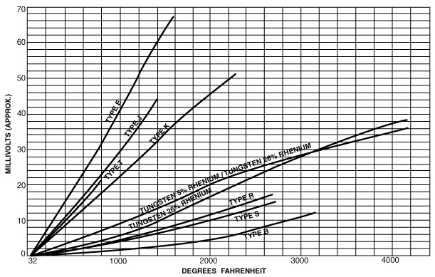
Note: EMF values for other calibrations available on request.
| T/C Material Types | |
|
E = CR/CN J = I/C K = C/A T = CU/CN |
R = Pt/Pt 13% Rh S = Pt/Pt 10% Rh B = Pt 30% Rh/Pt 6% Rh |