
Introduction to Thermocouples
The Principles and Features of Thermocouples
Today’s thermocouple designs are the result of many years of research and field experience. Together with quality instruments they provide the answer to thousands of temperature sensing and control problems.
The Seebeck Effect
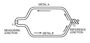
Basically, a thermocouple is a closed circuit formed of two dissimilar metallic conductors to produce an electromotive force (EMF) or voltage. The voltage causes a current to flow when heat is applied to one of the junctions. The current will continue to flow as long as the two junctions are at different temperatures. This is called the Seebeck effect, after T. J. Seebeck who discovered the principle.
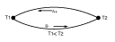
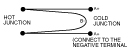
The direction of the current flow at the cooler of the two junctions (T1) determines polarity. For example, in Figure 2 when the current flows from a to B. a is considered positive.
The Pettier Effect
Peltier found that when current flows across the junction of two dissimilar metals the junction will either release heat or absorb it, depending on the direction the current is flowing. If the current flows in the same direction as the current produced in a thermocouple at the measuring junction, heat will be absorbed and heat will be released at the opposing (cold) junction. The amount of heat absorbed and released is proportional to the quantity of electricity flowing across the junction.
Thermoelectric Laws
A. a circuit of a single homogeneous wire cannot maintain a current by means of heat application alone.
B. In a circuit of two dissimilar homogeneous wires, if one junction is maintained at one temperature and the other junction at another, the resulting thermal EMF will be independent of the temperature gradient along the wires.
C. a third metal may be introduced into a circuit of two dissimilar homogeneous wires–with their measuring junction and cold junction maintained at different temperatures – without affecting the total EMF (voltage) in the circuit. This law, often called the law of intermediate metals, works in the following manner: In a circuit of two dissimilar homogeneous wires A & B with measuring junction and cold junction maintained at different temperatures, introduce the third metal C by cutting the a wire and inserting wire C making two additional junctions a to C. If C is uniform in temperature over its entire length, the total EMF in the circuit will be unaffected. This law can be applied, in various forms, to a thermocouple head where the thermocouple wires are connected to the extension wires through a copper or brass block.
Common Thermocouple Circuitry
Below are examples of the most common thermocouple circuitry.
1. Standard single thermocouple composed of two dissimilar wires and a single measuring junction:
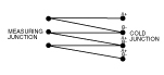
2. An averaging thermocouple composed two or more thermocouples connected in parallel to a common cold junction. The EMF generated will correspond to the mean of the temperature of the individual junctions, provided resistances of all the elements are equal.

3. a thermopile is composed of a series of two or more connected thermocouples. The resultant EMF will be the aggregate of all individual junctions.
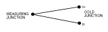
4. a Delta Thermocouple, also known as a differential thermocouple, is composed of two similar wires “A” joined to a single dissimilar wire “B” with the two measuring junctions normally at different temperatures. The resulting EMF will be the difference between the two junctions, commonly referred to as the differential temperature.
Note: At least one of the thermocouple junctions must be ungrounded and the measuring instrument must be of the differential type. a typical scale range might be: -150 to 0 to +150
Purpose of Connection Heads
The thermocouple connection or terminal head provides a positive electrical connection between the thermocouple and extension wires and provides a means of attachment for a protecting tube and extension wire conduit. The head contains a terminal block for all electrical connections. Connection heads are available for every application. Typical heads include a cast aluminum cover head, ideal for applications which must be completely weatherproof; a polypropylene head for extreme corrosion areas, explosion-proof conduit type.
Extension Wire Use
Extension wire is used to extend the thermocouple to the reference junction in the instrument. The wire is furnished as a matched pair of conductors with insulation designed to meet the service needs of a particular application.