
Calibration
Occasionally, the interchangeability tolerance listed for a sensor is unacceptable for an application. On those occasions there are three types of calibrations available. Thermo Sensors maintains a laboratory with equipment traceable to the National Bureau of Standards to furnish these calibrations.
1. If there is only one temperature of interest, or the interest is over a narrow range, elements can be selected by calibration to have a closer interchangeability tolerance of no more than .25% of the tem perature. This selection calibration makes field adjustment of the measurement instrument unnecessary when elements are changed in critical applications.
2. Elements can be calibrated at a particular temperature of interest. Also if there are temperatures of interest over a narrow range, a two or three point calibration will provide the user with information for interpolation within that range so that the measurement instrument can be adjusted.
3. a complete computer generated resistance/temperature table can be provided for a platinum sensor over the range of 0°C to its maximum useful temperature. These tables can be provided in °F or °C with temperature increments from .01° to 1° as specified by the customer.
Matched Pairs
When using two platinum sensors to measure the differential temperature of chilled water, standard ± 0.12% elements can produce an error as much as 0.6°C. Usually this is unacceptable in critical applications. In those cases, sensors having a differential of down to ± 0.6°C at 0°C or .25% of a selected temperature can be furnished by calibration at additional cost.
Lead Wire Compensation
Since the readout instrumentation for sensors is normally remoted considerable distances from the sensors themselves, it is important to consider and usually eliminate additional resistance imposed by the connecting wires. It is important that only the resistance change of the sensor be measured. To eliminate any change in lead resistance due to ambient changes, either a three or four wire connection should be used.
Most industrial applications are served well by using a three wire system while the four wire is common in laboratory environments.
Diagrams and comments relating to the four commonly used wiring systems are shown below.
2-Wire System
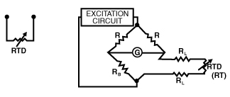
At balance RB will equal RT + 2RL giving an error equal to the two leads of the sensor connection. Depending on lead length and wire size the error may be negligible or profound.
3-Wire System
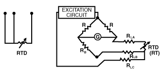
Industrial sensors commonly use this three wire connection system. For this system to be effective, all the leads (RLA, B, C) should be very near the same length and of the same gauge.
At balance:
RB = RLB = RT + RLA
RT = RB + RLB – RLA
Any error would be to the magnitude of the difference in resistance of RLA and RLB which should be negligible assuming the leads are the same length and gauge.
4-Wire System
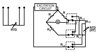
This system provides precision measurements. By switching the pairs of leads and averaging, you arrive at a value from which the lead resistance, thermal emf’s in the leads and resistance changes in the leads due to ambient variation has been eliminated.
Switch Position a At balance:
RB + RLC = RT + RLA
RT = RB + RLC – RLA
Switch Position B
At balance:
RB + RLA = RT + RLC
RT = RB + RLA = RLC
| < Previous |