
Bayonet Assemblies
Table 1 (style)
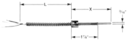
| Figure 1 | Bayonet with stainless steel armor |
 |
|
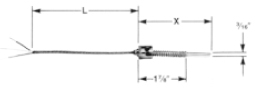
| Figure 2 | Bayonet with stainless steel overbraid |
 |
|
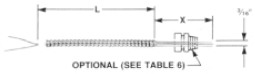
| Figure 3 | Rigid tube with stainless steel armor |
 |
|
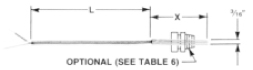
| Figure 4 | Rigid tube with stainless steel overbraid |
 |
|
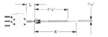
| Figure 5 | Rigid tube bayonet with male plug (only option “M” in Table 5 may be specified |
 |
|
| Straight |
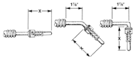 |
| Assemblies in figures 1-5 are available with straight, 45° or 90° angle configuration. Select in Table 1. |
| Order
Code |
Configuration | ||
| Straight | 45° | 90° | |
| Figure 1 | R111 | R145 | R190 |
| Figure 2 | R211 | R245 | R290 |
| Figure 3 | R311 | R345 | R390 |
| Figure 4 | R411 | R445 | R490 |
| Figure 5 | R511 | R545 | R590 |
Table 2 (sensing element options)
| Sensor Type | Order Code | |
| 2-Wire* | 3-Wire* | |
| 100ohm Platinum
.00385 T.C. (DIN 43760) (Most commonly used) |
A2 | A3 |
| Notes: | For dual element insert a “2”
in front of order Code. Example: 2A3 |
|
Table 3
Temperature Range Options
| Temperature Range | Order Code |
| -50 to +260°C
-50 to +500°F |
L |
| -50 to +400°C -50 to +750°F | S |
Table 4
Dimension Option
| “X” and “L” Lengths | Order Code |
| Refer to Figures 1-7 and specify
the lengths of “X” and “L” in inches. Insert in ordering sequence. See “How To Order” |
|
Table 5
End Terminations
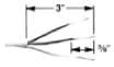
Insulated Leads-Striped |
B |

No. 8 Spade Lugs |
L |
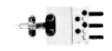
Male Plug |
M
Required for Figure 5. Optional for others. |
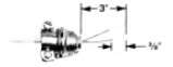
1/2″ BX Connector |
BX |
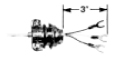
1/2″ BX Connector w/ #8 Lugs |
BXL |
Table 6
Options
| Style | Order Code |
| 1/8″ npt brass compression fitting for Figures 3 and 4 | B |
| 1/8″ npt stainless steel compression for Figures 3 and 4. | S |
| Mating female connector for end termination “M” in Table 5 | F |
How to Order
Make a selection from each table and specify “X” and “L” dimensions as shown below. Insert hyphens only where indicated.
| Style | – | Sensing Element | – | Temp. Range | – | Dimensions | – | Terminations | – | Options | ||
| R111 | A3 | L | (X) | Specify
in Inches |
(L) | M | F | |||||
| Table 1 | Table 2 | Table 3 | Table 4 | Table 5 | Table 6
(optional) |
|||||||
Table 13
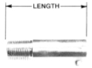
| Thread | Length | Part Number |
| 1/8NPT
1/8NPT 1/8NPT 3/8-24 3/8-24 3/8-24 |
7/8″
1-3/8″ 2-1/2″ 7/8″ 1-3/8″ 2-1/2″ |
3001-1
3001-2 3001-3 3001-4 3001-5 3001-6 |
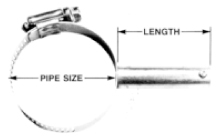
| Part Numbers | |||||||||
| Adapter Lengths | Pipe Clamp Sizes (IPS) | ||||||||
| 1/2″ | 3/4″ | 1-1/2″ | 2″ | 2-1/2″ | 3″ | 3-1/2″ – 4″ | 5″ | 6″ | |
| 1.875″ Standard | 3002-1 | 3002-2 | 3002-3 | 3002-4 | 3002-5 | 3002-6 | 3002-7 | 3002-8 | 3002-9 |
| 2-1/2″ | 3003-1 | 3003-2 | 3003-3 | 3003-4 | 3003-5 | 3003-6 | 3003-7 | 3003-8 | 3003-9 |
| 3″ | 3004-1 | 3004-2 | 3004-3 | 3004-4 | 3004-5 | 3004-6 | 3004-7 | 3004-8 | 3004-9 |
| 3-1/2″ | 3005-1 | 3005-2 | 3005-3 | 3005-4 | 3005-5 | 3005-6 | 3005-7 | 3005-8 | 3005-9 |
| 4″ | 3006-1 | 3006-2 | 3006-3 | 3006-4 | 3006-5 | 3006-6 | 3006-7 | 3006-8 | 3006-9 |
| 5-1/4″ | 3007-1 | 3007-2 | 3007-3 | 3007-4 | 3007-5 | 3007-6 | 3007-7 | 3007-8 | 3007-9 |
For New Installations:
The following formula may be used to determine the “X” dimensions of bayonet RTD.
For Threaded Adapters:
X = Depth of hole + adapter length + 1/2″.
For Pipe Clamp Adapters:
X = Adapter length + 3/4″
(This formula assumes the sensor is in surface contact with the pipe.)