
Product and Ordering Information
Table 7
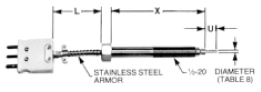
| Figure 1 | Immersion Bolt with Armor Extension |
 |
|
| “X” | “U” | Order Code | “X” | “U” | Order Code |
| 3″ | *** | R350-(U)*** | 6″ | *** | R350-(U)*** |
| Flush | R351 | Flush | R351 | ||
| 1/2″ | R352 | 1/2″ | R352 | ||
| 1″ | R353 | 1″ | R353 | ||
| 4″ | *** | R354-(U)*** | *** | *** | R354-(X)-U)*** |
| Flush | R355 | Flush | R355 | ||
| 1/2″ | R356 | 1/2″ | R356 | ||
| 1″ | R357 | 1″ | R357 | ||
|
***Insert desired length of “U” in inches and/or “X” in inches. Example: R350-1/4; R3512-8-1/4 |
|||||
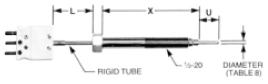
| Figure 2 | Immersion Bolt with Rigid Tube Extension |
 |
|
| “X” | “U” | Order Code | “X” | “U” | Order Code |
| 3″ | *** | R390-(U)*** | 6″ | *** | R398-(U)*** |
| Flush | R391 | Flush | R399 | ||
| 1/2″ | R392 | 1/2″ | R3910 | ||
| 1″ | R393 | 1″ | R3911 | ||
| 4″ | *** | R394-(U)*** | *** | *** | R3912-(X)-U)*** |
| Flush | R395 | Flush | R3913-(X) | ||
| 1/2″ | R396 | 1/2″ | R3914-(X) | ||
| 1″ | R397 | 1″ | R3915-(X) | ||
|
***Insert desired length of “U” in inches and/or “X” in inches. Example: R350-1/4; R3512-8-1/4 |
|||||
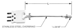
| Figure 3 | Nozzle Bolt with Stainless Steel Overbraided Extension |
 |
|
| Description | Fig. 3 (as shown) | Fig. 3 w/o. Male Plug | ||||||
| Description | R500 | R501 | ||||||
|
Mating Female Connectors Order Mating Female Connectors as a Separate Item
|
||||||||
Table 8
Sensor Diameter
| Diameter | Order Code |
| 1/8″ (.125″) | 2 |
| 3/16″ (.188) Standard | 3 |
| Do not use this table for “R500”, “R501” | |
Table 9
Sensing Element
| Sensor Type | Order Code | |
| 2-Wire* | 3-Wire* | |
|
100 OHM Platinum .00385 T. C. (DIN43760) (Most commonly used) |
A2 | A3 |
|
Note: All sensor are ± 0.12% @ °C Dual Elements are not available. |
||
Table 10
Temperature Range
| Temperature Range | Order Code |
|
-50 to + 260°C -58 to + 500°F |
L |
|
-50 to + 260°C -58 to + 500°F |
S |
Table 11
“L” Dimension
| “L” Dimension | Order Code |
|
Refer to Figures 1-3 and Specify “L” in inches and insert in ordering sequence. See “How to Order” |
|
How to Order
| Style | – | Sheath Diameter | – | Sensing Element | – | Temp. Range | – | Length | ||
| R353 | 3 | A3 | L | (X) |
Specify “L” in Inches |
(L) | ||||
| Table 7 | Table 8 | Table 9 | Table 10 | Table 11 | ||||||