Product and Ordering Information
Table A (cont.)
| Figure 7 | Figure 8 | |||
 |
 |
|||
| Figure 9 | Figure 10 | |||
 |
 |
|||
| Figure 11 | Figure 12 | |||
 |
 |
|||
| Figure 13 | ||||
 |
||||
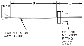
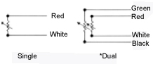
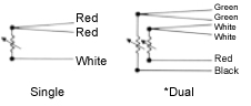
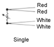
| Lead Insulation | Basic Order Code | ||||||
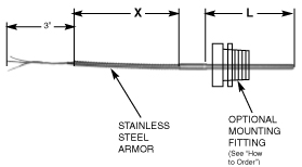
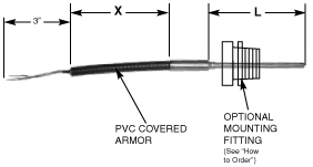
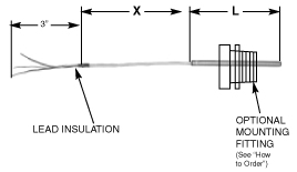
| Figure 7 | Figure 8 | Figure 9 | Figure 10 | Figure 11 | Figure 12 | Figure 13 | |
| FEP | TT (X) | TTS (X) | TTA (X) | TTP (X) | T (X) | TS (X) | TA (X) |
| Kapton | TK (X) | TKS (X) | TKA (X) | TKP (X) | K (X) | KS (X) | KA (X) |
| Polyvinyl | TP (X) | TPS (X) | TPA (X) | TPP (X) | P (X) | PS (X) | PA (X) |
| Fiberglass | TG (X) | TGS (X) | TGA (X) | TGP (X) | G (X) | GS (X) | GA (X) |
How to Order
Replace the “X” in “Basic” order code with desired lead extension Length in inches.
Example: TT48 for 48″ Lead Length
RTD Assembly Specifications
| Sensor Diameter | Order Code | |
| 1/8″ | (.125″) | 2 |
| 3/16″ | (.188″) | 3 |
| 1/4″ | (.250″)STD | 4 |
| 5/16″ | (.312″) | 5 |
| 3/8″ | (.375″) | 6 |
|
Resistance 0°C |
Material | Temperature Coefficient/Alpha (a) | Order Code | |
| Single Element | Dual Element | |||
| 100Ω | Platinum | .00385Ω/Ω°C | A | 2A |
| 100Ω | Platinum | .003916Ω/Ω°C | B | 2B |
| 100Ω | Platinum | .003902Ω/Ω°C | C | 2C |
|
98.129Ω (100Ωnom-) |
Platinum Sama Standard RC21-4-1966 |
.00392Ω/Ω°C | D | 2D |
| 120Ω | Nickel | .00672Ω/Ω°C | E | 2E |
| 9.035Ω | Copper | .00427Ω/Ω°C | F | 2F |
| Accuracy at 0°C | Order Code | |
| ± .12% | Class B | 1 |
| ± .06% | Class A | 2 |
| ± .03% | Lab Grade | 3 |
| ± .02% | Lab Grade | 4 |
| ± .01% | Lab Grade | 5 |
| Temperature Range | Order Code |
|
-50 to +250 Deg. C -58 to +482 Deg. F |
A |
|
-50 to +400 Deg. C -58 to +752 Deg. F |
B |
|
-50 to +660 Deg. C -58 to +1220 Deg. F |
C |
| Sheath Material | Order Code |
| 316 SS | 1 |
| Alloy 600 | 2 |
| Alloy C-276 | 3 |
| 2-Wire | Order Code A |
 |
|
| 3-Wire | Order Code B |
 |
|
| 4-Wire | Order Code C |
 |
|
|
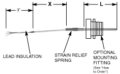
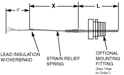
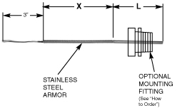
Specify “L” in Inches Length Not required when Thermowell is used. |
Optional Connections
(For extended lead types)
Table I (options)
| Description | Order Code | ||
 |
Spade Lugs for #8 Screw | L | |
 |
Male Plug | M | |
|
The connectors shown are for 3-wire single element assemblies. Two – 2 Pin connectors mounted in tandem will be furnished for both styles of 4-wire single element assemblies. Dual element assemblies will have the same connector arrangements except Doubled. |
|||
 |
|||
| Female Jack | F | ||
 |
Watertight connector | 1/2″ NPT | W1 |
| 3/4″ NPT | W3 | ||
 |
Watertight connector with lugs for #8 screws | 1/2″ NPT | WL1 |
| 3/4″ NPT | WL3 | ||
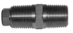
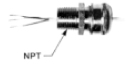
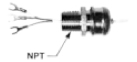
| Optional Mounting Fittings | ||
| Description | NPT | Order Code |
 |
1/8″ | 1AS |
| 1/4″ | 2AS | |
| 3/8″ | 3AS | |
| 1/2″ | 4AS | |
| 3/4″ | 6AS | |
|
For FEP readjustable insert, replace “A” with “R” Example: 4RS |
||
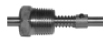
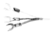
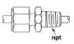
| Optional Spring-Loaded Devices | |
| Description | Order Code |
|
Adjustable Spring |
FP 275 |
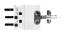
|
1/2″ NPT Double threaded adjustable hex bushing |
FP 240 |
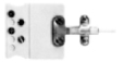
|
1/2″ NPT single threaded adjustable hex bushing |
SSL |