
Product and Ordering Information
The purpose of this design procedure is to enable the user to determine if a well selected for thermometry considerations is strong enough to withstand specific application conditions of temperature, pressure, velocity, and vibration. Well failures are caused by forces imposed by static pressure, steady state flow, and vibration. Separate evaluations of each of the above effects should be made in order to determine the limiting condition. This design procedure does not allow for effects due to corrosion or erosion.
The natural frequency of a well designed in accordance with Fig. 1.1 and of the dimensions given in Table 1.1 is given by the following equation:
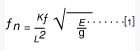
where
ƒn = natural frequency of the well at use temperature, cycles per sec
L = length of well as given in Fig. 1.1, in.
E = modulus of elasticity of well material at use temperature, psi
g = specific weight of well material at use temperature, lb per cu in.
Kƒ = a constant obtained from Table 1.2
The wake or Strouhal frequency is given by:
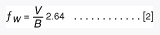
where ƒw = wake frequency, cycles per sec
V = fluid velocity, fps
B = diameter at tip (Fig. 1.1), in.
The ratio of wake to natural frequency (ƒw/ƒn) shall not exceed 0.8, and when this condition is met, the Magnification Factor, relationship of dynamic to static amplitude is given by:
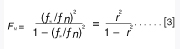
For r ≤ 0.8
where
FM = magnification factor, dimensionless
r = frequency ratio, (ƒw/ƒn), dimensionless
Stress Analysis
The maximum pressure that a thermometer well can withstand for a given material at a given temperature shall be computed from the following:

where
P = maximum allowable static gage pressure, psi
S = allowable stress for material at operating temperature as given in the ASME Boiler and Pressure Vessel or Piping Codes, psi
K1 = a stress constant obtained from Table 1.3.
The maximum length that a thermometer well can be made for a given service is dependent upon both vibratory and steady state stress. The necessity for keeping the frequency ratio at 0.8 or less imposes one limitation on maximum length. The other limitation is one of steady state stress considerations, as given by the following equation:
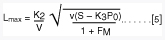
where
Lmax = maximum value of L (as shown in Fig. 1.1) for a given service, in.
V = fluid velocity, fps
v = specific volume of the fluid, cu ft per lb.
S = allowable stress for material at operating temperature as given in the ASME Boiler and Pressure vessel or Piping Codes, psi
P0 = static operating gage pressure, psi
FM = magnification factor as computed from Eq [3]
K2, K3 = stress constants obtained from Table 1.3
Table 1.1 well dimensions, in Inches
| Dimension | Nominal Size of Sensing Element |
| (1/4) | |
| A (minimum) | 13/16 |
| B (minimum) | 5/8 |
| d (minimum) | 0.254 |
| d (maximum) | 0.262 |
Fig. 1.1 power test code
Thermometer wells
|
Well Length L, in. |
Kƒ | Stress Constant | |
| 2-1/2 | 2.06 | K1 | 0.412 |
| 4-1/2 | 2.07 | K2 | 37.5 |
| 7-1/2 | 2.08 | K3 | 0.116 |
| 10-1/2 | 2.09 | ||
| 16 | 2.09 | ||
| 24 | 2.09 | ||
|
Table 1.2 values of Kƒ |
Table 1.3 values of stress constants |
||
*** Power Test Code Thermometer Wells, J. W. Murdock, Journal of Engineering for Power, Trans. ASME, vol. 81, 1959.